Analysis Results Reports
The Loads/Analysis tab is used to define project loadings and load combinations for one of the three analysis/design cases: Initial, Final and Final w/o Sway. You may also perform an analysis from this tab. (You can also select the Run Analysis command from the View menu or click the icon in the Toolbar.) After the analysis completes, the default analysis report will display in the Analysis Results screen.
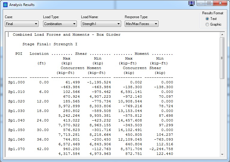
This screen can display both text and graphic analysis results. The window has four drop-down lists (five when graphical results are displayed), which allow you to select a variety of reports. The content of some of the drop-down lists is dependent on the current selection of one or more of the other drop-down lists. For example, if the currently selected analysis/design case does not have a live load defined, then Influence Lines, Truck/Lane and Live Load results will not be present in the Load Type drop-down list.
Total Results
The results presented in the analysis reports for non-live load results are total results. Total results represent the summation of responses due to a particular non-live loading from the time the loading enters the system up to and including the currently selected analysis/design case. CIP RC/PT Girder performs an incremental analysis in which the structure configuration and loadings for each analysis/design case is analyzed as a separate analysis.
For example, if a dead load (or added dead load and PT) is placed on the structure in the Initial case and a time-dependent loss type such as LRFD is selected, then the results for the loading for the Final case will be different than the Initial case because of creep affects. There will no difference in results if the Lump Sum loss type is selected. The results for the Initial and Final case due to post-tensioning for the Lump Sum loss type will be different due to the assumed lump sum loss of prestress between the Initial and Final cases.
Results for transient loadings, i.e., temperature, truck/lane, and live load are only available for the analysis/design case in which they are defined and, therefore, are incremental results by definition. For example, if you place a live load in the Final case, influence lines, raw truck/lane, and live load results will only be available for the Final case.
Load Types
One or all of the following types of loads will appear in the Load Type drop-down list depending what has been defined for a particular analysis/design case.
Dead Loads
Structure responses due to loadings placed in the Dead Load/DC Group on the Loads/Analysis tab will be available from the Dead Load load type.
Added Dead Loads
Structure responses due to loadings placed in the Superimposed Dead Load/DW Group will be available from the Added DL load type.
Internal Loads
Structure responses due to post-tensioning and shrinkage loadings will be available from the Internal load type. Responses due to shrinkage will be zero unless one of the time-dependent loss types is selected.
Temperature Loads
Structure responses due to loadings placed in the Temperature Load Group will be available from the Temperature load type. Uniform temperature rise and fall (TU) and Gradient rise and fall (TG) are the two types of temperature loadings that can be added to the Temperature Load Group.
Influence Lines, Truck/Lane, and Live Loads
These types of results will be available when a live load is placed in the Live Load Group.
Load Combinations
Load combination (group or limit state) results will be available from the Combination load type when combinations have been defined. Combination results will be available even if no combinations have been defined sinceCIP RC/PT Girder will automatically generate combinations.
Load Name
The content of the Load Name drop-down list will usually be the name of a loading either assigned by CIP RC/PT Girder, such as Dead Load-1, TempTU-1, PT: Tendon-1, or one renamed by the user. The exception to this rule is for influence lines in which the names of the Points-Of-Interest (POIs) will appear in this drop-down list, along with the All option.
Response Type
| Composite Forces | These are force results on the transformed section due to the selected loading. Post-tensioning is placed in the structure during the Initial case and becomes part of the cross section in the Final case. Rebar becomes part of the cross section in the Initial case only if the Transform Rebar option is selected in the Longitudinal Rebar Definitions dialog box. |
| Forces/Stresses | These are force and stress (top/bottom) results on the concrete box girder. The shear reported is for the composite section. |
| Displacements | These are horizontal, vertical and rotational displacements. |
| Reactions | These are horizontal, vertical and moment reactions between the abutments, piers and the superstructure, and between adjacent span segments at span hinges. |
| Min/Max Forces | These are minimized and maximized shear and moment results on the composite cross section. |
| Min/Max Stresses (not for Truck/Lane) | These are minimized and maximized, top and bottom stresses on the concrete box girder. |
| Min/Max Displacements | These are minimized and maximized, horizontal, vertical and rotational displacements. |
| Min/Max Reactions | These are minimized and maximized, horizontal, vertical and moment reactions. |